Implementing Angle Prediction
From a single microphone perspective, you can get some wind speed which we shall call A. Without a reference it is impossible to know the actual angle and for which gives actually a biased 'A'. For example, imagine microphone A reads that the wind speed as 13 miles per hour. It could actually be a 13 miles per hour wind hitting the microphone directly or maybe a 20 miles per hour wind that is hitting the microphone at a non-ideal angle. As you can see from the angle predictions, the angle of a constant wind speed does indeed cause the output to vary. This won't matter if it was used to measure wind speed in a vent or shaft because wind would only be forced one way, thus there would be no need for more than 1 mic and no need to sense for direction. For the weather box however, we needed to build something more general.
That is why we added 4 mics to sense direction, by checking the relationship of the output of each microphone.
Microphone Predicament
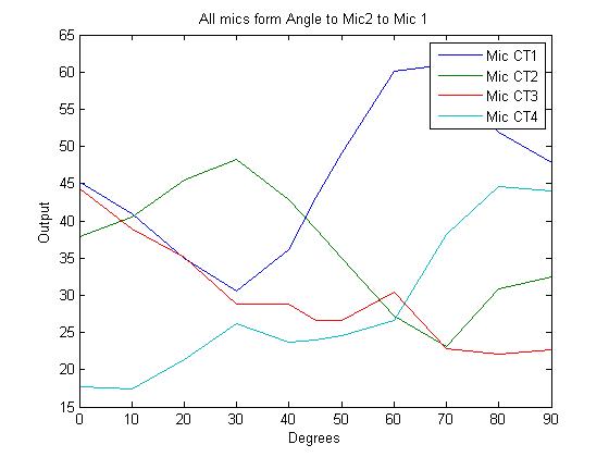
{Note that the current microphones we ordered in a decent number of batches are the arduino omnidirectional microphones which senses sound from all direction}. This causes some altercations from our original assumptions because we couldn't just take our y-axis mics and treat it as the A*sin(Θ), and the A*cos(Θ) for our x-axis mics. We tried to collect some raw data from the microphone and see if we could find a relationship between our multiple outputs and the angle of the wind. From this we took samples every 10 degrees and traveled from mic 2 (0 degrees/ directly to mic 2) to mic 1 (90 degrees/ directly to mic 1).
Degrees vs Output (From Mic 2 to Mic 1)
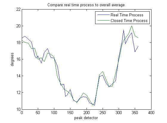
 Old Previous Data

To our surprise, the microphone that had the direct impact was not the highest mic. Right off the bat we remembered numerous previous data that also showed that the best angle would be a very slight amount of degree off from directly. As we modeled our old program by using the input and different trig functions, we treated these extra peaks and nulls as random noise. The naivety became our downfall because through multiple trials, these peaks and nulls from different speeds, fans and distances kept reoccurring. This brings even more troubles because we fit the actual wind speed to the output of the mic when the wind speed is directly facing a mic. If the wind came at an small angle that deviates from a direct hit, it would output a speed slightly larger which was not calibrated correctly. The actual closest mic to the angle of the fan doesn't actually overtake the next mic in amplitude until 15 degrees, and then it'll cross the 45 degree mark and then the same problem would happen except reflected on to the next incoming mic.
Mic Predicament Fix
What we did notice that was consistent, specially since sound attenuates at a fast rate was the farthest mic is always had the smallest output, and generally the second farthest away should be the second lowest output. We can now create a range, which gives some information and a range of tolerance. This will make things a lot easier because a lot of trigonometric functions are invertible between 0 and 90 degrees which is good to map a specific input to a specific output when trying to predict by taking a specific output to a specific input. If the wind comes exactly toward the mic however, the overall range band will keep flickering back and forth.
An example how this does the range is let us say we have 4 mics that point North, West, East and South. If the South mic is the lowest and East mic is the second lowest, the wind is coming from North West. If a wind comes exactly from the North, the output will probably flicker between North to West at some small angle to North to East at some small angle depending on the small little noises on the opposing mic that will pick up. Now we need to know the angle between North and West, but due to inconsistencies in the front 2 mics vs the sources, we would use the back 2 mics for prediction, hence in this case South and East.
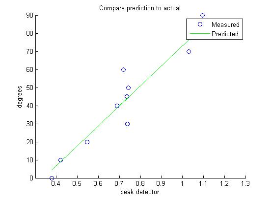
The most basic thing would be to find the angle in between would be the ratio of the 2 amplitudes. After fitting a couple of models, we chose to fit the angle with the arctan(lowest_mic/2nd_lowest_mic). Since the minimum switches off right between the half way marks of the mic, the actual range should be from 0 to 45 degrees (A→B 0 to 45 degrees, B→A 45 to 90 degrees). With this data we fitted a general line to arctan(mic4/mic3) to the degree of the fan hitting in respect to mic 2.
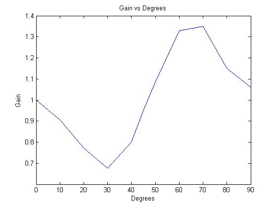
Using this model we predicted the angle. (Note at this point 12/17/2015 the accuracy of this prediction is questionable). Now that we got the angle, we can fix the gain problem. We want to fix the fact that we calibrated the wind speed with the reading from our sensors with the wind heading dead on. Since we can calculate for the angle, we can simply divide by the gain of the output that the angle created. We took our data of our outputs at multiple degrees and divided it by the output at 0 degrees which will equal the gain that the degree has created.
From this picture, we fitted a sinusoidal function (1-.3*sin(4t)). Now, assuming the gain caused by angle doesn't depend on the speed of the wind, we can just divide the output from our loudest mic, and divide it by the predicted induced gain from the angle. A drawback of this fix is now our output of wind speed is dependent on the output of our direction of wind and we are relying on only half of our mics to calculate for our angle.
Our most recent current block diagram is shown below.
Authors
Contributing authors:
Created by jeremygg on 2015/12/18 01:38.


