This is an old revision of the document!
=== Updated Boot loading Procedure (February 7, 2022):===
- links to tutorials:
- Copy the schematic below but instead of using two Arduino Boards use one Arduino Board as the programmer and the PCB as the target. On the PCB, pins MOSI, MISO and SCK are the same pins as digital pin 11, 12 and 13, respectively.
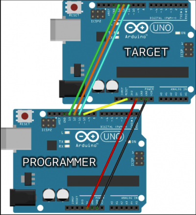
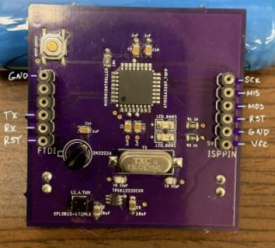
- Linked here is the pin-out for the PCB.
- Once finished wiring the Arduino and PCB, Open Arduino IDE
- Open Arduino ISP under: File → Examples → 11.ArduinoISP → ArduinoISP
- Tools should have the following configuration


- Upload code to Arduino Uno:
- Once completed, burn bootloader under tools
- Once bootload is done with no errors move onto uploading code using the FTDI
- Now, take out the microcontroller from the Arduino and connect the Arduino to the PCB as described below.
- Also, connect the XBEE to the PCB shown below

- There should be five wires connected the Arduino to the PCB. On the PCB, connect pins RX, TX , RESET, VCC, GND to TX, RX, RESET, 5V, GND to the Arduino, respectively. This is different from the Arduino tutorial link as TX and RX must be swapped.
- Open Arduino ISP under: File → Examples → 11.ArduinoISP → ArduinoISP
- Tools should have the following configuration
- Upload code to Arduino Uno:
- Once completed, burn bootloader under tools
- If there is an error, try change the Clock value to “Internal 8 MHz” then upload keeping all other settings the same. Then when the program fails change the clock value back to “External 16 MHz”
- If there were no errors, run a simple program to make sure it worked.
- Go to file → Examples → Basics → Fade and upload the code. Check and make sure the LED on the PCB is fading in and out. You can also try and upload your relay code to verify everything is working properly.
=== Troubleshoot Bootloading & FTDI Programming For: ===
 It should be noted that a no communication code 0x0000 could be a hardware or software issue.
 fastest way to verify a hardware issue is attempting to boot load a known good device.
Bare Bumblebee (List steps to troubleshoot boot load issues on bare bumblebee)
- Verified boot load settings in IDE with team Guava bread board. Had successful boot load.
- Attempted boot load of Bumblebees bread board. No communication 0x0000 unknown device.
- Switched known good Atmega328 chip from team Guava board to team Bumblebees board. Boot load
failed to communicate still.
- Boot loaded Team Apples Atmega328 chip on team Guavas board. Successful boot load.
- Removed all circuits not necessary for boot loading team Bumblebee board and attempted boot.
Verified circuits of bread board for boot loading Still no connection 0x0000.
- Changed 16 mega Hz clock as a failed clock would result in no communication. Still 0x0000
- Changed out two ceramic 22pF capacitors. Still no communication 0x0000.
- Changed out 1uF capacitor. Polarity of capacitor between ground and reset
pin 1 appears to have been reversed.
  Attempted boot load with successful communication on team Bumblebees bread board.

Bumblebee 4.0 (List steps to troubleshoot boot load issues on bumblebee 4.0)

    * Connected Bumblebee version 4.0 to IDE and attempted boot load. No communication unrecognized device 0x0000.
    * Circuits where checked for continuity and shorts and all appear to be ok.
    * Upon contacting lab mates a recommendation was made to changed Bod voltage from 2.7 volts
      to 4.3 volts. After this successful communication was
     established with Bumblebee version 4.0 and boot load appeared to take.
    * Connected Bumblebee version 4.1 and attempted boot loading. No communication 0x0000.
    * Attempted to upload sketch to version 4.0 to verify boot load was successful with no success.
 Bumblebee 4.1 (List steps to troubleshoot boot load issues on bumblebee 4.0)

  * Connected Bumblebee version 4.1 to IDE and attempted boot load. No communication unrecognized device 0x0000.
    * Circuits where checked for continuity and shorts and all appear to be ok.
    * Bod voltage changed from 2.7 volts to 4.3 as with version 4.0 Bumblebee still no
      communication 0x0000.
    * Attempted to upload sketch to version 4.0 to verify boot load was successful with no
     success.
     At this point a sketch upload needs to be performed to version 4.0 to verify boot loading
     was successful.
=== How to bootload PCB boards: ===
- Open up board schematic & board layout (we used v4.0 but same process for both versions)
- Determine correct ISP pins for bootloading
- Connect ISP pins to Arduino Uno
- Connect Arduino Uno to computer
- Open Arduino IDE
- Open Arduino ISP under: File→Examples→11.ArduinoISP→ArduinoISP
- Upload code to Arduino Uno: Tools→Port→Port # (Arduino Uno)→Upload
- Once upload to Arduino Uno is complete go to Tools and select correct configuration
- Tools should have the following configuration (Note: We are using the MiniCore Library to setup bootload/FTDI programming upload)

- Once completed, burn bootloader under tools
- Once bootload is done with no errors move onto uploading code using the FTDI
=== Troubleshooting Bootloading Information:===
- Arduino to a Microcontroller: https://www.arduino.cc/en/Tutorial/BuiltInExamples/ArduinoToBreadboard
- Minicore Guide: https://github.com/MCUdude/MiniCore#wiring-reference
- Circuit IO Guide: https://www.circuito.io/blog/atmega328p-bootloader/
- Nick Gammon Bootloading: https://www.gammon.com.au/bootloader
- More Nick Gammon: https://github.com/nickgammon/arduino_sketches