Wind Sensor Team Meeting-March 24, 2017
Attended: Mengyuan, Creighton, Scott
Acoustic Wind Sensor
- Updates:
- Replaced microphones on the pcb and conducted tests again
- Re-began testing 4-microphone set-up
- Unexpectedly, when the microphones were faced perpendicular to the direction of the wind, they still output the same wind speed
- This is most likely due to the fact that the microphones are omni-directional
- Results for a single microphone set-up are also still inconsistent on the pcb.
- To Do:
- Solder microphones onto a perforated board to see if the traces on the pcb were the problem.
- Build wind channels for the microphones
- Will probably entail recalculating coefficients, since the funnels will probably affect the output of the microphones
Ultrasonic Wind Sensor
- Updates:
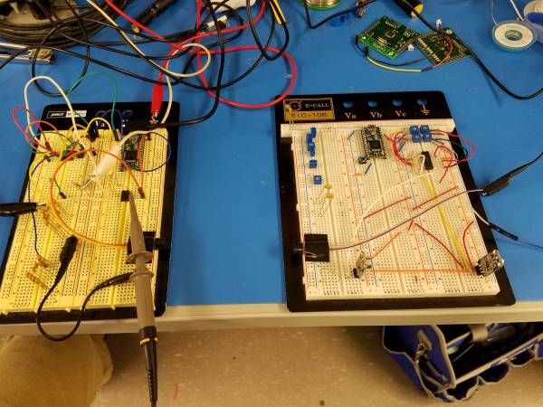
- Built an amplifier and placed it in between the 40kHz square wave output of the 555 timer circuit and the emitter. Hooked up the signal at the output of the amplifier to an oscilloscope as well as the signal at the receiver. Our experimental setup as well as the results are shown below:
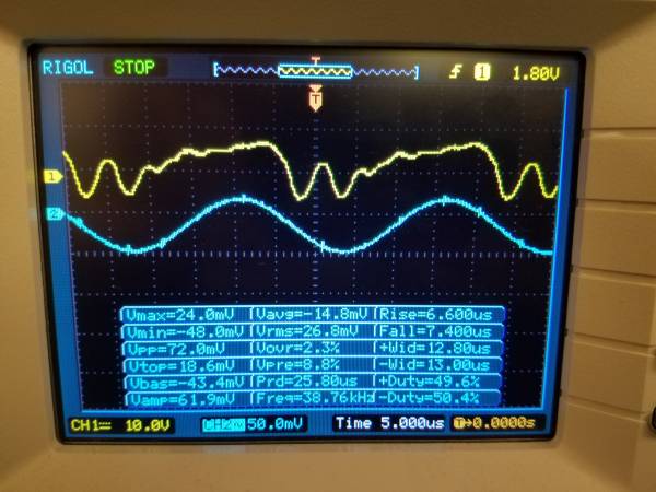
- Our results were problematic. For one, the output of the amplifier was heavily distorted (it should've been a clean square wave), though the amplitude was still around 13Vpp (which it should've been). Furthermore, the received signal was much weaker than expected. We were only getting 72mVpp, when we expected much more.
- Upon further investigation, we realized that we probably exceeded the slew rate of the amplifier. Since square waves have high slopes (typical rise time is 100ns), and we have somewhere around 15Vpp, that's 1.5 GV/s (going from -7.5V to +7.5V in 100ns). However, exceeding the slew rate shouldn't have distorted our signal to that extent. May need to investigate further.
- Developed an algorithm that involves using the Teensy to generate the 40kHz square wave instead of using the 555 timer. This is mainly due to avoid the possibility of a current bottleneck with trying to drive the transducer using the 555 timer.
- The algorithm involves the Teeny sending 10 25us pulses and then using thresholding and ADC to record the pulses. Since the tof of a pulse is longer than the time it takes the Teensy to send the pulses, we don't have to worry about potentially trying to record while still sending. Average a bunch of samples and we should have a result.
- Quickly wrote a program to generate a 40kHz square wave using the Teensy's TimerOne library. Observing it on the oscilloscope, the square wave looked pretty clean. We then tried to drive the emitter using the Teensy's square wave and observing the results. The results are below:
- For some reason, when moving the transducers farther apart, sometimes we are getting an increase in amplitude, rather than a decrease. It seems like we're getting a good amplitude around 6-8cm so we should test that distance some more and redesign our algorithm if need be.
- The breadboards aren't completely level and this threw our amplitudes off. We have to find another breadboard that's level with the one we have now.
- Did a bit of research into TDCs (time-to-digital converters). These chips are designed specifically for measuring the time between two events.
- One TDC chip we're looking at is the TDC1000 by Texas Instruments (http://www.ti.com/lit/ds/symlink/tdc1000-q1.pdf). It features the ability to drive two emitters and receivers, as well as the ability to generate the signal for the emitter and count until the receiver hears the signal.
- One drawback with the TDC1000 is that we need to provide it with a clock signal. Furthermore, the clock we provide it has to be a power of 2 multiple of the frequency we wish to use to drive our emitters (40kHz). We're thinking of using a crystal oscillator as the clock, but we'll need to find a matching frequency.
- Another thing is that we'll need to figure out how to communicate with the TDC1000 using the Teensy.
- To Do:
- Continue development on the Teensy.
- Our biggest issue right now is figuring out what's going to drive the emitter. Is it going to be the Teensy with the new algorithm, or are we going to stick with using an external chip?
- Furthermore, we need to start designing an amplifier on the receiver that can amplify our signal and block out the majority of the noise.
- Look into using a TDC chip for the time tof measurement.
- See viability of TDC 1000. Also look into crystal oscillators with a good frequency.
- Research other TDC chips. See if there is one that is compatible with Arduino.


Authors
Contributing authors:
Created by mwu on 2017/03/25 02:05.